Configure GUIslice for ESP8266 & ESP32
This guide describes the steps to configure the GUIslice library for Arduino and related devices
- ESP8266 (ESP8266)
- NodeMCU (ESP8266)
- Adafruit HUZZAH (ESP8266)
- ESP32 (ESP32)
- Adafruit HUZZAH32 (ESP32)
For ESP8266 / ESP32 devices, GUIslice can be built within the Arduino IDE.
In the case of ESP8266 / ESP32 devices, it is strongly recommended that users utilize bodmer's TFT_eSPI graphics library as the display driver. His library has been highly optimized for these devices.
If using TFT_eSPI, the GUIslice configuration should enable the following display driver: DRV_DISP_TFT_ESPI. In this mode, GUIslice will depend on the correct display configuration in the TFT_eSPI library.
Displays that support touch will generally advertise a separate driver associated with the capacitive or resistive touch capability. Look for:
| Touch Device | Type | GSLC_DRV_TOUCH_* setting |
|---|---|---|
| None | n/a | DRV_TOUCH_NONE |
| STMPE610 | resistive | DRV_TOUCH_ADA_STMPE610 |
| FT6206 | capacitive | DRV_TOUCH_ADA_FT6206 |
| XPT2046 | resistive | DRV_TOUCH_TFT_ESPI |
This touch driver will be later used in GUIslice's DRV_TOUCH_* setting.
Before attempting to run GUIslice, it is essential that the standalone graphics example included in the TFT_eSPI display library has been configured and runs correctly. If the TFT_eSPI example code doesn't work, GUIslice will not work, so please don't skip this step!
In all cases, the TFT_eSPI base graphics library needs to be installed first.
First, follow the directions in the TFT_eSPI library to configure your User_Setup file according to your display and associated wiring. Then, open the TFT_eSPI graphics example:
- File → Examples → TFT_eSPI → 320x240 → TFT_graphicstest_one_lib (or select an example matching your resolution)
- Confirm that the example successfully compiles and runs, showing a series of display patterns
GUIslice expects to read configuration settings from the following location: GUIslice/src/GUIslice_config_ard.h
The developers of the Arduino IDE aimed to make it as easy as possible for beginners, but the downside is that advanced libraries such as GUIslice require an extra step in order to override a library's configuration defaults.
Locate the GUIslice library within the Arduino libraries folder. The libraries folder is located within the Arduino IDE sketchbook directory. To find your sketchbook directory, select File → Preferences in the Arduino IDE and look for the "Sketchbook location" (eg. C:\Users\<username>\Documents\Arduino). The libraries folder will be a folder with the same name inside the Sketchbook folder.

- Typically the libraries folder would therefore be:
-
C:\Users\<username>\Documents\Arduino\libraries(for Windows)
Within the Arduino libraries folder, you should find the GUIslice library that you installed earlier. It will either be named GUIslice or GUIslice-master, depending on whether you used the Arduino IDE Library Manager or manually downloaded the latest version from GitHub.
The configuration file (GUIslice_config_ard.h) is located within the \src folder within the GUIslice library folder. It is important to confirm that you can locate this file so that modifications can be made later. For example, the full path to this config file may be:
C:\Users\<username>\Documents\Arduino\libraries\GUIslice-master\src\GUIslice_config_ard.h
It is recommended to make a backup copy of your original GUIslice_config_ard.h file before making changes (although one can always download a new copy from the repository later if needed).
Many of the GUIslice configuration options are dictated by either #define <mode> <value> or #define <mode> lines within the config file.
In some cases the config file provides multiple related #define <mode> lines (such as DRV_DISP_*, with one line uncommented, and the remainder of the related modes commented out (with //). In order to change one of these config options, uncomment the desired mode and then comment out (or delete) the other related modes.
For other configuration modes, a single line #define <mode> <value> is provided, with a value of 0 or 1 dictating that the feature is disabled or enabled, respectively. Simply change the value between 0 and 1 as needed.
From this point onwards, references will be made to "enabling" or "disabling" a config setting, with the above convention used.
GUIslice supports a wide range of display and touch hardware in addition to the accompanying software drivers. We need to start by ensuring that GUIslice imports the appropriate display and touch drivers.
Since the TFT_eSPI library's User_Setup already takes care of the physical configuration, there is no wiring / pinout to be configured within GUIslice. An example GUIslice config file has been created for TFT_eSPI users.
THE FOLLOWING NEEDS TO BE UPDATED
Look in the GUIslice /configs directory for an example device + display combination that matches your setup. If one exists, copy this file (cfg###-<cpu>-<display>.h) over top of the default GUIslice_config_ard.h file in the library's /src folder from Step 3. The easiest way to do this is:
- Rename the existing
GUIslice_config_ard.hfile toGUIslice_config_ard.h.bak - Copy the example config
cfg###-xxx-yyy.hinto the/srcfolder (which had theGUIslice_config_ard.hfile) - Rename the example config to
GUIslice_config_ard.h
Note that more example configurations will be added to the library over time, and users are encouraged to submit their own (if it is a combination that hasn't been provided yet).
In many cases, a matching Example Configuration won't be available, and therefore the GUIslice pin configuration needs to be updated to match the settings that worked in the Adafruit graphicstest example earlier.
Ensure Adafruit-GFX is used as the main driver mode by enabling DRV_DISP_ADAGFX and disabling any others.
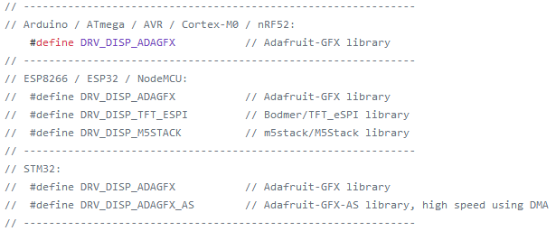
Now, select the appropriate Adafruit display driver matching the controller in Step 1, by enabling one of the DRV_DISP_ADAGFX_* modes.
Finally, we need to ensure that the configuration matches the wiring pinout.
- Look for the line that instantiates the Adafruit display (such as Adafruit_ILI9341):

- Note the settings on
TFT_DC,TFT_CS, etc. that worked earlier. Copy these same values to the GUIslice_config_ard.h'sADAGFX_PIN_*settings: 
Now that we have the basic driver and display settings configured, it is time to test the basic operation of the GUIslice library.
In order to facilitate debug, it is best to enable debug output and disable touch support temporarily. Modify the GUIslice_config_ard.h file in the following way:
- Look for
#define DEBUG_ERR. Change the value from0to1. This step enables debug messages out the Serial Monitor at the expense of extra memory consumption. For Arduino devices tight on memory, it is expected that DEBUG_ERR will disabled later (with0) once the library is confirmed to operate as expected. - Look for the
#define DRV_TOUCH_*lines. Change the enabledDRV_TOUCH_*setting toDRV_TOUCH_NONE. Once display operation is confirmed as functional, theDRV_TOUCH_*setting can be changed back to the expected driver.
In the Arduino IDE, open up the ex01_ard_basic example:
- File → Examples → GUIslice → arduino → ex01_ard_basic
Enable the Serial Monitor in the Arduino IDE:
- Tools → Serial Monitor
- Change the baud rate to 9600 (located in bottom right corner of window) as this is the default used in the GUIslice examples (look for the
Serial.begin(9600);line). If you don't set a baud rate that matches the sketch serial initialization, random characters may be written to the display.
Run the sketch with Sketch → Upload
- Look for any error messages reported on the Serial Monitor
- See if the display shows a gray background with write-framed box:

If the above display test works properly, then it is time to enable the touch driver and test again (if a touch device is used).
- Revert the
DRV_TOUCH_*line so that the correct touch driver is enabled (comment outDRV_TOUCH_NONE).
- In the Arduino IDE, open up the ex02_ard_btn_txt example:
- File → Examples → GUIslice → arduino → ex02_ard_btn_txt
- Upload and confirm that a button responds to touch presses OK. Note that after releasing a touch on the button that the sketch is expected to "quit" and stop responding. Resetting the device will start the test again.

If the touch presses don't appear to line up as expected, it may be necessary to adjust the touch-to-display mapping setting.
- In most cases this can be done by changing the
GSLC_TOUCH_ROTATEsetting to a value 0,1,2 or 3. These settings will adjust the flip and swapping of touch axes versus the display orientation. - To further help debug any touch handling, you can enable the
DBG_TOUCHfeature which will display yellow markers corresponding to where the display is detecting touch presses (according to the above mapping settings). - Also, note that resistive displays may require calibration to be performed in order to ensure the touch presses line up as expected.
If the display and touch appear to be working correctly, experiment by loading up the other examples provided with GUIslice. For arduino devices, these can be loaded from the Arduino IDE under:
- File → Examples → GUIslice → arduino → ex01_ard_* (normal memory examples)
- File → Examples → GUIslice → arduino_min → ex01_ardmin_* (minimum memory examples)
In the repository, the above examples are located in the /examples/ directory.
This section will be added soon