Calibration Guides
Many calibrations: bed tramming, z-offset, mesh leveling... could be affected by temperature. If your printer does not have hardware modifications (stock) you can use the firmware as it is. For Neo, Max, Plus printers, or if you made any hardware changes (bed, hotend, fan duct, etc.) you must adjust some physical parameters. If your custom fan duct tutorial indicates to change the home offsets then read this: How to set the home offsets. Also check the extended calibrations to properly set up your extruder/hotend.
If you are using a host like Pronterface or Octoprint remember to set the serial port to 250000 baud.
If you have a CR-Touch check the notes about disabling HS mode, if you intend to use a mesh larger than 5x5.
If you have modified your printer with a custom fan duct, your probe (CR/3D/BLTouch) has other than stock offsets, or if you have a bigger bed or axis, you could require some physical adjustments.
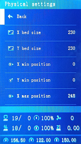
- Set your physical dimensions (Min/Max X/Y/Z Positions) before changing the Bed size (
Advanced > Physical settings). Check if you need to correct the parking position (Advanced > Set Home Offsets > Park Head). - Set your probe X/Y offsets (
Advanced > Probe Settings) using this guide to get Accurate Probe Offsets. - Set your mesh inset (
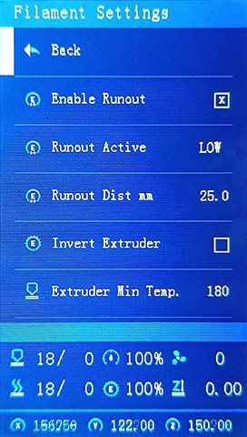
Advanced > Mesh leveling > Mesh inset) according to your physical dimensions and probe offsets, you can automatically do it pressing Maximize area and then Center area. Always set the mesh inset only after setting physical limits and bed size. If you are using UBL, save your mesh settings in the current mesh slot. - If you have a Runout sensor, configure the active mode (
Prepare > Filament Management > Filament Settings > Runout Active), if not, leave the "Enabled Runout" disabled. - Store your settings and Reboot printer. | (Reboot is optional)
- Check if your slicer's printer profile has the same physical settings.
This firmware has the X/Y Min/Max position calibrated for an Aquila or Ender-3 V2/S1 without modifications.
If you have a Neo / Max or have some physical mod, you'll most likely need to adjust the physical settings.
- Load default settings or set
Min X/Y Positionto 0 andMax X/Y Positionto a larger number than your bed size. - Run
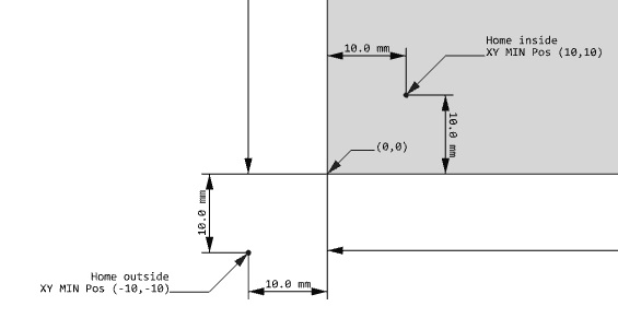
Auto Homeand move your nozzle (Prepare > Move Axis) to the (0,0) position.
Is your nozzle over the bed corner?
Inside or Outside of the bed?
If the nozzle is outside of the bed, the value of Min position is NEGATIVE. - Move your X/Y axis (
Prepare > Move Axis) until the tip of the nozzle is over the front left corner of the bed, that determines theX/Y MIN Position, set the proper values inControl > Physical Settings. - Save changes, auto home again.
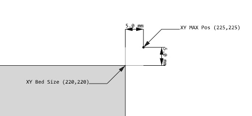
If you move axes to (0,0), the nozzle will be on the corner of the bed. - Move the nozzle until you reach the other side of the bed, that is your bed size.
- Move the nozzle until you reach some physical limitation, that is your X/Y MAX position.
- If your bed is 220x220 move your axes to the position (110,110) the nozzle will be over the center of the bed.
- Use
Maximize Meshand thenCenter MeshfromLevel > Mesh Settings > Mesh Insetsub menu.
If you are using UBL, save your mesh settings in the current mesh slot. - From a console: send the command
G30 X110 Y110(assuming a bed size of 220x220), the probe will go to the center of the bed.
Correct the probe offset if needed. - Again use
Maximize Meshand thenCenter Meshin Advanced Settings.
If you are using UBL, save your mesh settings in the current mesh slot. - Store your settings (
Control > Store Settings), or sendM500.
Reboot printer (Optional).
- Preheat your printer and wait for thermal stabilization (
Prepare > Preheat) - Do Bed Tramming (
Prepare > Bed Tramming) - Build a mesh leveling (
Level >Build Manual Mesh/Auto Build Mesh) - If you have a probe, set your probe Z-offset (
Prepare > Z probe wizard)
- Hotend and bed MPC/PID (
Control > Hotend MPC/PID > Bed PID) - Material Preheat temperatures (
Control > Temperature > Preheat) - Axes Maximum Speeds, Acceleration, Jerk, Steps (
Control > Motion) - Park position (
Control > Set Home Offsets > Park Head) - Set the filament length between your runout sensor and extruder (
Prepare > Filament Management > Runout Dist mm) - Load and Unload filament length (
Prepare > Filament Management > Load/Unload mm)
- Slicer start/end G-code scripts.
- Slicer post processing scripts.
- Octoprint G-code scripts.
- G-code Thumbnail extension
There are several sources for information about of how to do these calibrations on the web and YouTube.
Get the latest firmware ![]()
Use the Firmware Selector
-
Generate a G-code image preview
- Slicer post processing scripts -
Update LCD Display ICON's
- How to install the DWIN_SET - How to install the firmware
- https://teachingtechyt.github.io/calibration.html - Great for all around calibrations
- https://ellis3dp.com/Print-Tuning-Guide/ - Secondary guide for extra references
- https://youtu.be/xzQjtWhg9VE - Video guide for E-steps and Flow calibration
Some the pages and images in this Wiki were copied from https://github.com/mriscoc/Ender3V2S1/wiki