DataSheet Motor DataSheet Motor 2
A stepper motor can move in accurate, fixed angle increments known as steps. The advantage of steppers over DC motors is that you can achieve much higher precision and control over the movement. The downside of using steppers is that they are a bit more complex to control than servos and DC motors.
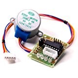
The 28BYJ-48 is a small, cheap, 5 volt, geared stepping motor. These stepping motors are widely used to control things like automated blinds, A/C units and are mass-produced.
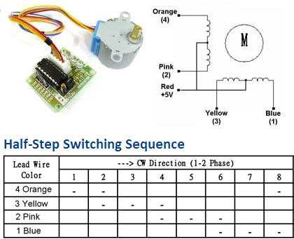
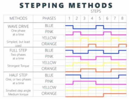
The motor has 4 coils of wire that are powered in a sequence to make the magnetic motor shaft spin. When using the full-step method, 2 of the 4 coils are powered at each step. The 28BYH-48 datasheet specifies that the preferred method for driving this stepper is using the half-step method, where we first power coil 1 only, then coil 1 and 2 together, then coil 2 only and so on…With 4 coils, this means 8 different signals, like so
In addition to full step and half step there is also wave drive method. Where one coil at a time is powered (like a wave) All three methods are available in this library. Full gives the most torque. Half gives less torque but more accuracy and wave drive is best for low power applications. half step mode is recommend for most projects.
Half-step mode: 8 step control signal sequence 5.625 degrees per step / 64-step control signal sequence per one revolution of the internal motor shaft
Full Step mode and wave drive: 4-step control signal sequence 11.25 degrees per step / 32-step control signal sequence per one revolution of the internal motor shaft
Gear ratio Manufacturer specifies 64:1. These means that in the recommended half-step mode we will have: 64 steps per motor rotation x 64 gear ratio = 4096 steps per full revolution (approximately). 4096/8 = 512 steps control signal sequence for motor to rotate one revolution due to gear division
So for Full step and wave drive, 32 X 64 = 2048 , 2048/4 = 512 steps
(steps per motor rotation X gear ratio) / Number of steps control signal sequence = steps control signal sequence for motor to rotate one revolution
The delay time setting between steps, recommend set to 0.001 second for half-step and 0.01 second for full and wave. The user can set it to whatever works for their application. It was noted in testing that .001 is too low for full and wave to function.
To calculate Number of steps control signal sequence per degree (512/360) = 1.422222)) So to turn motor 180 degree (180*1.4222) = ~256 steps
The ULN2003 stepper motor driver board allows you to easily control the 28BYJ-48 stepper motor. One side of the board side has a 5 wire socket where the cable from the stepper motor hooks up and 4 LEDs to indicate which coil is currently powered.
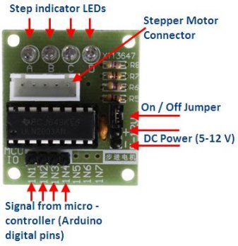
Connect the ULN2003 driver IN1, IN2, IN3 and IN4 to 4 GPIO pins on raspberry pi. These GPIO pins will be in a list of 4 in the software where [IN1 , IN2 , IN3 ,IN4] = [GPIO0 , GPIO1, GPIO2 , GPIO3] Connect the positive lead from a decent 5V power source “+” pin of the ULN2003 driver and the ground to the “-” pin. Make sure that the “on/off” jumper next to the “-” pin is on. If you power from raspberry pi connect the grounds together. It is ok to power one motor from pi 5v rail.
This detailed video explains more.
The library file RpiMotorLib.py contains the class which controls the motor. The test file in the test folder is called BYJ_Motor_Test.py.
When initialize class pass a name and motor type, The class is called BYJMotor. NB Set to motor type to 28BYJ for this component
BYJMotor(name, motor_type)
mymotortest = RpiMotorLib.BYJMotor("MyMotorOne", "28BYJ")| ID | Name | Type | Default | Help |
|---|---|---|---|---|
| (1) | name | string | BYJMotorX | motor_id |
| (2) | motor_type | string | 28BYJ | Calculate degree in verbose output 2 options , Nema and 28BYJ. 28BYJ for this component |
The main function is called motor_run- moves stepper motor based on 7 inputs.
mymotortest.motor_run(GPIOPins, wait, steps, counterclockwise, verbose, steptype, initdelay)| ID | Name | Type | Help |
|---|---|---|---|
| (1) | GpioPins, | List of ints 4 long, | 4 GPIO pins to connect to motor controller, GPIOPins[0] is plugged into Pin 1 on the stepper motor. [18, 23, 24, 25] |
| (2) | wait, | float, default=0.001, | Time to wait(in seconds) between steps. |
| (3) | steps, | int, default=512, | Number of step control signal sequence to take. Default is one revolution 512 |
| (4) | ccwise (counterclockwise), | bool default=False | Turn stepper counterclockwise |
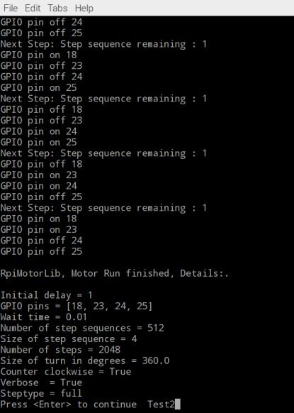
| (5) | verbose, | bool default=False | Write pin actions and provide verbose output |
| (6) | steptype, | string , default="half" | Type of drive to step motor 3 options "full" = fullstep "half" = half step "wave" = wave driven |
| (7) | initdelay, | float, default=1mS, | Initial delay after GPIO pins initialized but before motor is moved, gives time for GPIO to initialize. |
Example: To run A stepper motor connected to GPIO pins 18, 23, 24, 25 (18-IN1 23-IN2 24-IN3, 25-IN4) for step delay of .01 second for 100-step control signal sequence, in clockwise direction, verbose output off , in half step mode, with an init start delay of 50mS
The second function is called to stop the motor when the motor is moving. motor_stop(), if you wish to stop motor before the end of its run. You can also stop it with keyboard interrupt.
import RPi.GPIO as GPIO

# import the library
from RpiMotorLib import RpiMotorLib

GpioPins = [18, 23, 24, 25]

# Declare an named instance of class pass a name and motor type
mymotortest = RpiMotorLib.BYJMotor("MyMotorOne", "28BYJ")

# call the function , pass the parameters
mymotortest.motor_run(GpioPins , .01, 100, False, False, "half", .05)
If verbose is set to True various information on pin output and status is outputted to screen at the end of a run