The “RISC-V based MYTH (Microprocessor for You in Thirty Hours)” workshop provides a structured introduction to RISC-V architecture, covering software-to-hardware concepts through hands-on labs. Participants begin with C programming, GCC compilation, and Spike simulation before progressing to number systems and assembly programming. The workshop delves into combinational and sequential logic, pipeline implementation, and microarchitecture of a single-cycle RISC-V CPU. Labs include instruction decoding, register file operations, ALU implementation, and control flow hazards. The final stages focus on load-store instructions, memory management, and CPU testbench development, offering comprehensive learning experience in microprocessor design and verification. This course is divided into 5 days, the summary of these days are given below

Price: $25
RISC-V is an open-source instruction set architecture (ISA) that defines the basic operations a processor can perform. It's a "blueprint" for designing and building processors, offering a modular and extensible foundation for a wide range of applications, from embedded systems to high-performance computing.
Note
- Before moving on, you should have to know that all the tools like Linux, Spike, GNU compiler etc. are given separately to the student by the facilator after buying this course.
- All the projects in makerchip are made by the RISC-V/Calculater starter code which is present in the RISC-V_MYTH_Workshop repository you can click the RISC-V/Calculater starter link present in the repository and make projects from there only.
Day 1: Introduction to RISC-V ISA and GNU compiler toolchain
The binary number system contains only two numbers that are 0 and 1 and a bit is the digit of a binary number a group og 8 bits is called a byte and a group of 32 bits is called a word. Similarly a group of 64 bits is called a doubleword.
If i a have a 2-bit binary number the number of possible pattern for these two numbers are 00,01,10,11. Only these are the 4 combinations of a 2-bit binary number. The number of possiblities of binary number having n number of bits can be calculated by the following formula:
2^n suppose i have a 5-bit number the number of possiblities is 2 * 2 * 2 * 2 * 2 = 32 possiblities

In binary, an unsigned number is a representation of a non-negative integer, meaning it only represents positive whole numbers and zero. It doesn't have a sign bit to indicate positivity or negativity. Like 00000001 is a binary number equivalent to decimal number 1 it does not have a sign bit to indicate whether this number is positive or negative in its MSD (Most significant Bit).

In the binary system, a signed number representation uses the most significant bit (MSB) to indicate the sign of the number. If the MSB is 0, the number is positive; if it's 1, the number is negative. Like 10000010 is a 8-bit number the MSB of this number is 1
so the number will be in negative the rest of the number detemines the original value of the number which is 0.

1. Simple c program for adding numbers between 1 to n
#include <stdio.h>

int main() {
int i, sum = 0, n = 5;
for (i=1; i <= n; ++i) {
sum += i; }
printf("Sum of numbers from 1 to %d is %d\n", n, sum);
return 0;

}
This is the c code for adding numbers, make a file named 1ton.c and paste this in that file.
Steps to run this
-
Open the linux terminal and type
gcc 1ton.c -
And then type
./a.out
Then you will see the following output results

2. Simulation of the same 1ton program but with Spike
Run the following steps in terminal:
-
Open the terminal and type
riscv64-unknown-elf-gcc -Ofast -mabi=lp64 -march=rv64i -o 1ton.o 1ton.c -
Then type
spike pk 1ton.o
Then you should see the same result as:

Day 2: Introduction to ABI and basic verification flow
An Application Binary Interface (ABI) is a standard that defines the interface between compiled applications and the operating system, or between different binary modules. ABIs define the rules that compilers and assemblers must follow when generating binary code, ensuring that different code modules can be linked together and executed seamlessly.
Let’s look at an example load doubleword instruction below, which loads data into x8 register from memory, whose base address is present in register x23 and offset is ‘16’. The way a computer sees this instruction is through a 32-bit binary pattern.

Focus on ‘rs2’ and ‘rs1’. They have 5 bits. Practically, to keep design simple, all registers in a RISC-V architecture is represented by 5-bit binary pattern. Now the calculation is easy. 5-bits to represent registers, which means total number of registers is 2^5 = 32 registers
1. simulating the 1 to n adder but using ABI
Run the following steps in the terminal:
-
Open the terminal and make a file names 1to9_custom.c
-
and type this in it
#include <stdio.h> extern int load(int x, int y); int main() { int result = 0; int count = 2; result = load(0x0, count+1); printf("Sum of number from 1 to %d is %d\n", count, result); } -
Also make another file named load.S. And type this in it
.section .text .global load .type load, @function load: add a4, a0, zero //Initialize sum register a4 with 0x0 add a2, a0, a1 // store count of 10 in register a2. Register a1 is loaded with 0xa (decimal 10) from main program add a3, a0, zero // initialize intermediate sum register a3 by 0 loop: add a4, a3, a4 // Incremental addition addi a3, a3, 1 // Increment intermediate register by 1 blt a3, a2, loop // If a3 is less than a2, branch to label named <loop> add a0, a4, zero // Store final result to register a0 so that it can be read by main program ret -
Then open the terminal and type this after going to the folder in which you have made the two files.
riscv64-unknown-elf-gcc -Ofast -mabi=lp64 -march=rv64i -o 1to9_custom.o 1to9_custom.c load.S -
Then type
spike pk 1to9_custom.o
Then you will see the following results after this:

Day 3: Digital Logic with TL-Verilog and Makerchip
There are 3 main types of logic gates of which other more logic gates are made. These are AND, OR & NOT. The function of these gates are given below:


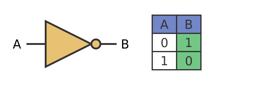
Logic gate is a fundamental building block in digital circuits, acting as a simple electronic switch or circuit that operates on binary inputs (0 or 1) to produce a binary output based on a specific logical rule. These gates implement Boolean algebra and are crucial for creating more complex digital systems like computers and other electronic devices. From these we can make more gates such as NAND,NOR,XOR and XNOR etc.
A combinational logic circuit is a type of digital circuit where the output at any given moment depends on the current combination of its inputs. It lacks memory, meaning the output is not influenced by the past states of the inputs. These circuits are built using logic gates like AND, OR, NOT, NAND, and NOR.

A sequential logic circuit is a digital circuit whose output depends not only on the present input but also on the past inputs and the internal state of the circuit. It incorporates memory elements, like flip-flops or latches, to store the previous state, allowing the circuit to "remember" past inputs. This contrasts with combinational logic, where the output is solely determined by the current inputs.

In digital electronics, a flip-flop is a fundamental memory circuit that can store a single bit of information (0 or 1) and can be toggled between these two states. It's like a basic switch that can be flipped on or off, retaining that state until an external signal (like a clock pulse) triggers a change. Flip-flops are bistable devices, meaning they have two stable states. They can hold a specific binary value (0 or 1) until a control signal causes them to change.

Pipelined logic, or pipelining, is a technique in computer architecture and digital circuit design that increases throughput by dividing a task into multiple stages and executing them in parallel.

Validity is the device meets the needs and requirements of its intended users and the intended use environment. In a chip there are maximum things that are not useful and sit idle in the chip, but the power still goes in them, which is a wastage of electricity. Validity fixes this problem by eliminating the non-useful gates.
1. Combinational calculator
-
Go to Makerchip and click on launch makerchip IDE.
-
Go to editor and place the below TL-Verilog in place of //...
$sum[31:0] = $val1[31:0] + $val2[31:0]; $diff[31:0] = $val1[31:0] - $val2[31:0]; $prod[31:0] = $val1[31:0] * $val2[31:0]; $quot[31:0] = $val1[31:0] / $val2[31:0]; $out[31:0] = $op[0] ? $sum : $op[1] ? $diff : $op[2] ? $prod : $qout ; -
Then click on 'compile'.

2. Sequential calculator
-
Go to Makerchip and click on launch makerchip IDE.
-
Go to editor and place the below TL-Verilog in place of //...
$sum[31:0] = $val1[31:0] + $val2[31:0]; $diff[31:0] = $val1[31:0] - $val2[31:0]; $prod[31:0] = $val1[31:0] * $val2[31:0]; $quot[31:0] = $val1[31:0] / $val2[31:0]; $out[31:0] = $op[0] ? $sum : $op[1] ? $diff : $op[2] ? $prod : $qout ; $out[31:0] = $val1[31:0] -
Then click on 'compile'.

3. Fibonacci Sequence
The Fibonacci Sequence is a sequence of whole numbers starting with two 1s, where each subsequent value in the sequence is the sum of the previous two values.
-
Go to Makerchip and click on launch makerchip IDE.
-
Go to editor and place the below TL-Verilog in place of //...
$val[15:0] = $reset ? 1 : >>1$val + >>2$val; -
Then click on 'compile'.

4. Pythagorean Theorem Pipeline
-
Go to Makerchip and click on launch makerchip IDE.
-
Go to editor and place the below TL-Verilog in place of //...
|calc @0 $valid = & $rand_valid[1:0]; // Valid with 1/4 probability // (& over two random bits). // DUT (Design Under Test) |calc ?$valid // Pythagoras's Theorem @1 $aa_sq[7:0] = $aa[3:0] ** 2; $bb_sq[7:0] = $bb[3:0] ** 2; @2 $cc_sq[8:0] = $aa_sq + $bb_sq; @3 $cc[4:0] = sqrt($cc_sq); -
Then click on 'compile'.

4. Final claculator with vaidity and memory
-
Go to Makerchip and click on launch makerchip IDE.
-
Go to editor and place the below TL-Verilog in place of //...
|calc @0 $reset = *reset; @1 $valid[0:0] = $reset ? '0 : >>1$valid + 1; $valid_or_reset = $valid || $reset; $val2[31:0] = $rand2; $val1[31:0] = >>2$out; ?$valid_or_reset @1 $sum[31:0] = $val2[31:0] + $val1[31:0]; $diff[31:0] = $val2[31:0] - $val1[31:0]; $prod[31:0] = $val2[31:0] * $val1[31:0]; $div[31:0] = $val2[31:0] / $val1[31:0]; @2 ?$valid_or_reset @2 $out[31:0] = $reset ? '0: $op[2:0] == 0 ? $sum : $op[2:0] == 1 ? $diff : $op[2:0] == 2 ? $prod : $op[2:0] == 3 ? $div : $op[2:0] == 4 ? >>2$mem : >>2$out; $mem[31:0] = $reset ? '0: $op[2:0] == 5 ? $val1: >>2$mem; -
Then click on 'compile'.
Day 4: Basic RISC-V CPU microarchitecture

In RISC-V, the PC MUX (Program Counter Multiplexer) is a circuit that selects the next instruction to be executed based on various factors, including the type of instruction.
In RISC-V architecture, IMEM Rd refers to the Read operation from the Instruction Memory (IMEM). This operation fetches the instruction from memory, given an address provided by the Program Counter (PC), and sends it to the processor.
In RISC-V, the decoder is a crucial component that translates binary instruction codes into the control signals needed for the processor to execute the instruction.
These are the register in RISC-V for read and write memory. Their are 32 registers like this in a RISC-V microachitecture.
ALU stands for Arithmetic Logic Unit, a fundamental component of a computer's central processing unit (CPU). It's responsible for performing arithmetic operations (like addition, subtraction, multiplication, division) and logical operations (like AND, OR, NOT, XOR) on binary data.
1. Fetch and Decode
-
Go to Makerchip and click on launch makerchip IDE.
-
Go to editor and place the below TL-Verilog in place of //...
|cpu @0 $reset = *reset; $pc[31:0] = >>1$reset ? '0 : (>>1$pc + 32'd4); @1 $imem_rd_en = ! $reset; $imem_rd_addr[M4_IMEM_INDEX_CNT - 1:0] = $pc[M4_IMEM_INDEX_CNT + 1:2]; $instr[31:0] = $imem_rd_data[31:0]; $is_i_instr = $instr[6:2] ==? 5'b0000x || $instr[6:2] ==? 5'b001x0 || $instr[6:2] ==? 5'b11001 || $instr[6:2] ==? 5'b00100; $is_r_instr = $instr[6:2] ==? 5'b01011 || $instr[6:2] ==? 5'b011x0 || $instr[6:2] ==? 5'b10100; $is_s_instr = $instr[6:2] ==? 5'b0100x; $is_b_instr = $instr[6:2] ==? 5'b11000; $is_j_instr = $instr[6:2] ==? 5'b11011; $is_u_instr = $instr[6:2] ==? 5'b0x101; $imm[31:0] = $is_i_instr ? { {21{$instr[31]}}, $instr[30:20] } : $is_s_instr ? { {21{$instr[31]}}, $instr[30:25], $instr[11:7] } : $is_b_instr ? { {20{$instr[31]}}, $instr[7], $instr[31:25], $instr[11:8], 1'b0 } : $is_u_instr ? { $instr[31:12] , 12'b0 } : $is_j_instr ? { {12{$instr[31]}}, $instr[19:12], $instr[20], $instr[30:21], 1'b0 } : 32'b0 ; $rs1[4:0] = $instr[19:15]; $rs2[4:0] = $instr[24:20]; $rd[4:0] = $instr[11:7]; $funct7[6:0] = $instr[31:25]; $funct3[2:0] = $instr[14:12]; $opcode[6:0] = $instr[6:0]; $rs1_valid = $is_r_instr || $is_i_instr || $is_s_instr || $is_b_instr ; ?$rs1_valid $rs1[4:0] = $instr[19:15]; $rs2_valid = $is_r_instr || $is_s_instr || $is_b_instr ; ?$rs2_valid $rs2[4:0] = $instr[24:20]; $rd_valid = $is_r_instr || $is_i_instr || $is_u_instr || $is_j_instr; ?$rd_valid $rd[4:0] = $instr[11:7]; $funct7_valid = $is_r_instr ; ?$funct7_valid $funct7[6:0] = $instr[31:25]; $funct3_valid = $is_r_instr || $is_i_instr || $is_s_instr || $is_b_instr; ?$funct3_valid $funct3[2:0] = $instr[14:12]; $opcode_valid = $is_i_instr || $is_r_instr || $is_s_instr || $is_b_instr || $is_j_instr || $is_u_instr; ?$opcode_valid $opcode[6:0] = $instr[6:0]; $dec_bits[10:0] = { $funct7[5], $funct3, $opcode }; $is_add = $dec_bits ==? 11'b0_000_0110011; $is_addi = $dec_bits ==? 11'bx_000_0010011; $is_beq = $dec_bits ==? 11'bx_000_1100011; $is_bne = $dec_bits ==? 11'bx_001_1100011; $is_blt = $dec_bits ==? 11'bx_100_1100011; $is_bge = $dec_bits ==? 11'bx_101_1100011; $is_bltu = $dec_bits ==? 11'bx_110_1100011; $is_bgeu = $dec_bits ==? 11'bx_111_1100011; -
Then click on 'compile'.

This TL-Verilog is used for making a basic RISC-V CPU architecture but only from the PC to the decoder.
2. Half-completed RISC-V based CPU which performs addition of number 1 to 9
-
Go to Makerchip and click on launch makerchip IDE.
-
Go to editor and place the below TL-Verilog in place of //...
|cpu @0 $reset = *reset; $pc[31:0] = (>>1$reset) ? 32'd0 : (>>1$pc + 32'd4); @1 $imem_rd_addr[M4_IMEM_INDEX_CNT - 1:0] = $pc[M4_IMEM_INDEX_CNT + 1:2]; $imem_rd_en = !$reset; $instr[31:0] = $imem_rd_data[31:0]; $is_i_instr = $instr[6:2] ==? 5'b0000x || $instr[6:2] ==? 5'b001x0 || $instr[6:2] ==? 5'b11001 || $instr[6:2] ==? 5'b00100; $is_r_instr = $instr[6:2] ==? 5'b01011 || $instr[6:2] ==? 5'b011x0 || $instr[6:2] ==? 5'b10100; $is_s_instr = $instr[6:2] ==? 5'b0100x; $is_b_instr = $instr[6:2] ==? 5'b11000; $is_j_instr = $instr[6:2] ==? 5'b11011; $is_u_instr = $instr[6:2] ==? 5'b0x101; $imm[31:0] = $is_i_instr ? { {21{$instr[31]}}, $instr[30:20] } : $is_s_instr ? { {21{$instr[31]}}, $instr[30:25], $instr[11:7] } : $is_b_instr ? { {20{$instr[31]}}, $instr[7], $instr[31:25], $instr[11:8], 1'b0 } : $is_u_instr ? { $instr[31:12] , 12'b0 } : $is_j_instr ? { {12{$instr[31]}}, $instr[19:12], $instr[20], $instr[30:21], 1'b0 } : 32'b0 ; $rs1_valid = $is_r_instr || $is_i_instr || $is_s_instr || $is_b_instr ; ?$rs1_valid $rs1[4:0] = $instr[19:15]; $rs2_valid = $is_r_instr || $is_s_instr || $is_b_instr ; ?$rs2_valid $rs2[4:0] = $instr[24:20]; $rd_valid = $is_r_instr || $is_i_instr || $is_u_instr || $is_j_instr; ?$rd_valid $rd[4:0] = $instr[11:7]; $funct7_valid = $is_r_instr ; ?$funct7_valid $funct7[6:0] = $instr[31:25]; $funct3_valid = $is_r_instr || $is_i_instr || $is_s_instr || $is_b_instr; ?$funct3_valid $funct3[2:0] = $instr[14:12]; $opcode_valid = $is_i_instr || $is_r_instr || $is_s_instr || $is_b_instr || $is_j_instr || $is_u_instr; ?$opcode_valid $opcode[6:0] = $instr[6:0]; $dec_bits[10:0] = { $funct7[5], $funct3, $opcode }; $is_add = $dec_bits == 11'b0_000_0110011; $is_addi = $dec_bits ==? 11'bx_000_0010011; $is_beq = $dec_bits ==? 11'bx_000_1100011; $is_bne = $dec_bits ==? 11'bx_001_1100011; $is_blt = $dec_bits ==? 11'bx_100_1100011; $is_bge = $dec_bits ==? 11'bx_101_1100011; $is_bltu = $dec_bits ==? 11'bx_110_1100011; $is_bgeu = $dec_bits ==? 11'bx_111_1100011; //read register file $rf_wr_en = $rd_valid; $rf_wr_index[4:0] = $rd; $rf_rd_en1 = $rs1_valid; $rf_rd_index1[4:0] = $rs1; $rf_rd_en2 = $rs2_valid; $rf_rd_index2[4:0] = $rs2; $src1_value[31:0] = $rf_rd_data1; $src2_value[31:0] = $rf_rd_data2; //ALU $result[31:0] = $is_addi ? ($src1_value + $imm) : $is_add ? ($src1_value + $src2_value) : 32'bx; $taken_br = (! $is_b_instr) ? 1'b0 : $is_beq ? ($src1_value == $src2_value) : $is_bne ? ($src1_value != $src2_value) : $is_blt ? ( ($src1_value < $src2_value) ^ ($src1_value[31] != $src2_value[31]) ) : $is_bge ? ( ($src1_value >= $src2_value) ^ ($src1_value[31] != $src2_value[31]) ) : $is_bltu ? ($src1_value < $src2_value) : $is_bgeu ? ($src1_value >= $src2_value) : 1'b0; $br_tgt_pc[31:0] = $pc + $imm; -
Then click on 'compile'
This TL-Verilog code is the final code for a basic 1 to 9 summer with the write and read register, ALU, Branch etc.

Day4.final.mp4
Day 5: Complete Pipelined RISC-V CPU micro-architecture
This is the link to my work CPU
-
Go to Makerchip and click on launch makerchip IDE.
-
Go to editor and place the below TL-Verilog in place of //...
|cpu @0 $reset = *reset; $pc[31:0] = >>1$reset ? '0: >>3$valid_taken_br || >>3$is_jal && >>3$valid_jump ? >>3$br_tgt_pc : >>3$is_jalr && >>3$valid_jump ? >>3$jalr_tgt_pc : >>3$valid_load? >>3$inc_pc: >>1$inc_pc; $imem_rd_addr[M4_IMEM_INDEX_CNT - 1:0] = $pc[M4_IMEM_INDEX_CNT + 1:2]; $imem_rd_en = !$reset; @1 *passed = |cpu/xreg[10]>>5$value == (1+2+3+4+5+6+7+8+9); $instr[31:0] = $imem_rd_data; $inc_pc[31:0] = $pc + 4; $is_i_instr = $instr[6:2] ==? 5'b0000x || $instr[6:2] ==? 5'b001x0 || $instr[6:2] ==? 5'b11001 || $instr[6:2] ==? 5'b00100; $is_r_instr = $instr[6:2] ==? 5'b01011 || $instr[6:2] ==? 5'b011x0 || $instr[6:2] ==? 5'b10100; $is_s_instr = $instr[6:2] ==? 5'b0100x; $is_b_instr = $instr[6:2] ==? 5'b11000; $is_j_instr = $instr[6:2] ==? 5'b11011; $is_u_instr = $instr[6:2] ==? 5'b0x101; $imm[31:0] = $is_i_instr ? { {21{$instr[31]}}, $instr[30:20] } : $is_s_instr ? { {21{$instr[31]}}, $instr[30:25], $instr[11:7] } : $is_b_instr ? { {20{$instr[31]}}, $instr[7], $instr[30:25], $instr[11:8], 1'b0 } : $is_u_instr ? { $instr[31:12] , 12'b0 } : $is_j_instr ? { {12{$instr[31]}}, $instr[19:12], $instr[20], $instr[30:21], 1'b0 } : 32'b0 ; $opcode_valid = $is_i_instr || $is_r_instr || $is_s_instr || $is_b_instr || $is_j_instr || $is_u_instr; ?$opcode_valid $opcode[6:0] = $instr[6:0]; $rs1_valid = $is_r_instr || $is_i_instr || $is_s_instr || $is_b_instr; ?$rs1_valid $rs1[4:0] = $instr[19:15]; $rs2_valid = $is_r_instr || $is_s_instr || $is_b_instr; ?$rs2_valid $rs2[4:0] = $instr[24:20]; $funct7_valid = $is_r_instr; ?$funct7_valid $funct7[6:0] = $instr[31:25]; $rd_valid = $is_r_instr || $is_i_instr || $is_u_instr || $is_j_instr; ?$rd_valid $rd[4:0] = $instr[11:7]; $funct3_valid = $is_r_instr || $is_i_instr || $is_s_instr || $is_b_instr; ?$funct3_valid $funct3[2:0] = $instr[14:12]; $dec_bits[11:0] = {$funct7[5],$funct3,$opcode}; $is_beq = $dec_bits ==? 11'bx_000_1100011; $is_bne = $dec_bits ==? 11'bx_001_1100011; $is_blt = $dec_bits ==? 11'bx_100_1100011; $is_bge = $dec_bits ==? 11'bx_101_1100011; $is_bltu = $dec_bits ==? 11'bx_110_1100011; $is_bgeu = $dec_bits ==? 11'bx_111_1100011; $is_addi = $dec_bits ==? 11'bx_000_0010011; $is_add = $dec_bits == 11'b0_000_0110011; $is_load = $dec_bits ==? 11'bx_xxx_0000011; $is_lui = $dec_bits ==? 11'bx_xxx_0110111; $is_auipc = $dec_bits ==? 11'bx_xxx_0010111; $is_jal = $dec_bits ==? 11'bx_xxx_1101111; $is_jalr = $dec_bits ==? 11'bx_000_1100111; $is_sb = $dec_bits ==? 11'bx_000_0100011; $is_sh = $dec_bits ==? 11'bx_001_0100011; $is_sw = $dec_bits ==? 11'bx_010_0100011; $is_slti = $dec_bits ==? 11'bx_010_0010011; $is_sltiu = $dec_bits ==? 11'bx_011_0010011; $is_xori = $dec_bits ==? 11'bx_100_0010011; $is_ori = $dec_bits ==? 11'bx_110_0010011; $is_andi = $dec_bits ==? 11'bx_111_0010011; $is_slli = $dec_bits ==? 11'b0_001_0010011; $is_srli = $dec_bits ==? 11'b0_101_0010011; $is_srai = $dec_bits ==? 11'b1_101_0010011; $is_sub = $dec_bits ==? 11'b1_000_0110011; $is_sll = $dec_bits ==? 11'b0_001_0110011; $is_slt = $dec_bits ==? 11'b0_010_0110011; $is_sltu = $dec_bits ==? 11'b0_011_0110011; $is_xor = $dec_bits ==? 11'b0_100_0110011; $is_srl = $dec_bits ==? 11'b0_101_0110011; $is_sra = $dec_bits ==? 11'b1_101_0110011; $is_or = $dec_bits ==? 11'b0_110_0110011; $is_and = $dec_bits ==? 11'b0_111_0110011; @2 $br_tgt_pc[31:0] = $pc + $imm; $rf_rd_en1 = $rs1_valid; $rf_rd_index1[4:0] = $rs1; $rf_rd_en2 = $rs2_valid; $rf_rd_index2[4:0] = $rs2; $src1_value[31:0] = (>>1$rf_wr_index == $rf_rd_index1) && >>1$rf_wr_en ? >>1$rf_wr_data : $rf_rd_data1; $src2_value[31:0] = (>>1$rf_wr_index == $rf_rd_index2) && >>1$rf_wr_en ? >>1$rf_wr_data : $rf_rd_data2; @3 $sltu_rslt = $src1_value < $src2_value; $sltiu_rslt = $src1_value < $imm; $result[31:0] = $is_addi || $is_load || $is_s_instr? $src1_value + $imm : $is_add ? $src1_value + $src2_value: $is_andi ? $src1_value & $imm: $is_ori ? $src1_value | $imm: $is_xori ? $src1_value ^ $imm: $is_slli ? $src1_value << $imm[5:0]: $is_srli ? $src1_value >> $imm[5:0]: $is_and ? $src1_value & $src2_value: $is_or ? $src1_value | $src2_value: $is_xor ? $src1_value ^ $src2_value: $is_sub ? $src1_value - $src2_value: $is_sll ? $src1_value << $src2_value[4:0]: $is_srl ? $src1_value >> $src2_value[4:0]: $is_sltu ? $src1_value < $src2_value: $is_sltiu ? $src1_value < $imm: $is_lui ? {$imm[31:12],'0}: $is_auipc ? $pc + $imm : $is_jal ? $pc + 4 : $is_jalr ? $pc + 4 : $is_srai ? { {32{$src1_value[31]}}, $src1_value} >> $imm[4:0]: $is_slt ? ($src1_value[31] == $src2_value[31]) ? $sltu_rslt : {31'b0, $src1_value[31]}: $is_slti ? ($src1_value[31] == $imm[31]) ? $sltiu_rslt : {31'b0, $src1_value[31]}: $is_sra ? { {32{$src1_value[31]}}, $src1_value} >> $src2_value[4:0]: 32'bx; $taken_br = $is_beq ? ($src1_value == $src2_value) : $is_bne ? ($src1_value != $src2_value) : $is_blt ? ($src1_value < $src2_value) ^ ($src1_value[31] != $src2_value[31]) : $is_bge ? ($src1_value >= $src2_value) ^ ($src1_value[31] != $src2_value[31]) : $is_bltu ? ($src1_value < $src2_value) : $is_bgeu ? ($src1_value >= $src2_value) : 1'b0; $valid_taken_br = $valid && $taken_br; $valid_load = $valid && $is_load; $is_jump = $is_jal || $is_jalr; $valid_jump = $is_jump && $valid; $valid = !(>>1$valid_taken_br || >>2$valid_taken_br || >>1$valid_load || >>2$valid_load || >>1$valid_jump || >>2$valid_jump) ; $jalr_tgt_pc[31:0] = $src1_value + $imm; $rf_wr_en = $rd!='0 && $rd_valid && $valid ; $rf_wr_index[4:0] = >>2$valid_load ? >>2$rd : $rd; $rf_wr_data[31:0] = >>2$valid_load ? >>2$ld_data: $result ; @4 $dmem_wr_en = $is_s_instr && $valid; $dmem_addr[3:0] = $result[5:2]; $dmem_wr_data[31:0] = $src2_value; $dmem_rd_en = $is_load; @5 $ld_data[31:0] = $dmem_rd_data; -
Then click on 'compile'.

Day.5.final.mp4
Note
To implement this RISC-V core in VSDSquadronFM FPGA, this is my another repository
This project is licensed under the MIT License - see the LICENSE file for details.
I would thank to Kunal Ghosh sir who guided us over this workshop and also taught us the first two days of this workshop. I will also express my gratitude to Steve Hoover sir who taught us in the last 3 days. And also thank to VSD and Redwood EDA for organizing this workshop.